Light Coils
MRI with fully optical data and power transmission
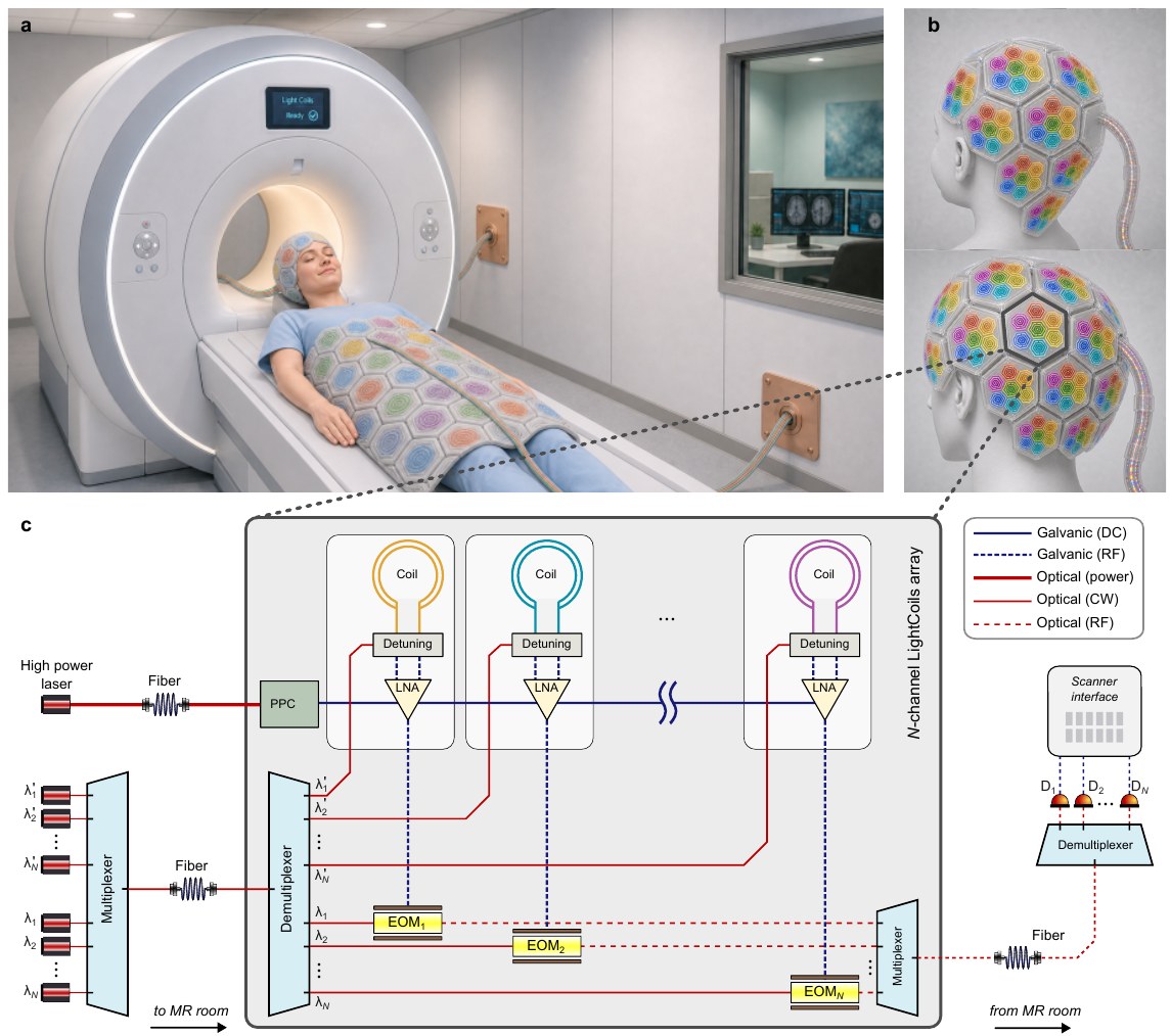
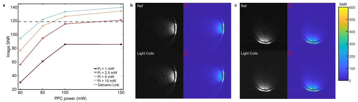
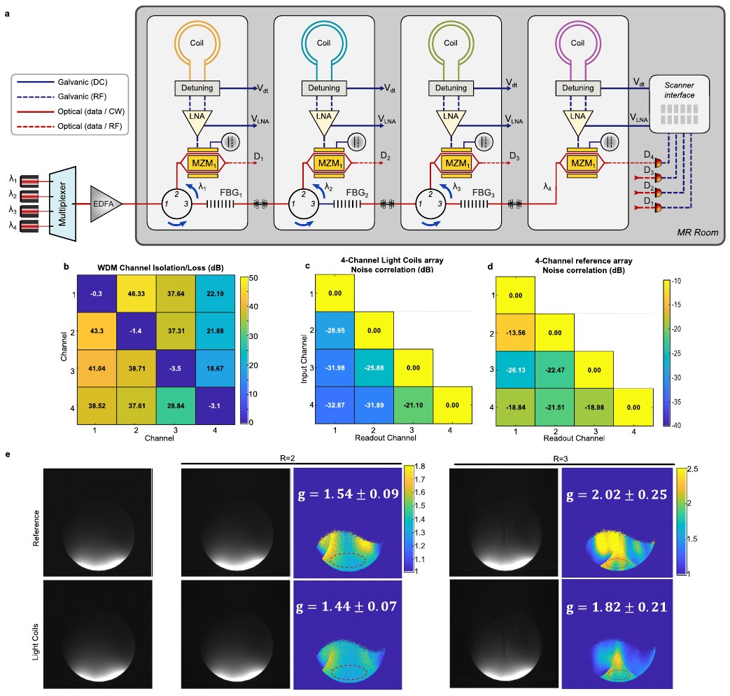
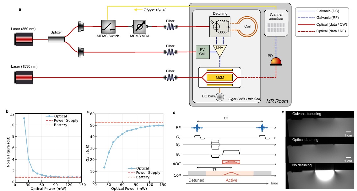
Light Coils are MRI receive coils that are powered, read out and detuned entirely over optical fibre, with no galvanic cables between the coil array and the scanner. We show in vivo human brain imaging at 3 T with SNR comparable to a conventional coaxial readout, and a 4-channel array multiplexed over a single fibre.
Zining Liu†, Morteza Teymoori†, Jakob Gerlach, Reza Aghabagheri, Henning Helmers, Michael Bock, Çağlar Ataman, Ali Caglar Özen
†Equal contribution. University of Freiburg (Radiology · IMTEK) and Fraunhofer ISE.
Why it matters
Faster MRI relies on dense receive arrays: more coil elements mean more SNR and higher parallel-imaging acceleration. But every element needs coaxial cables for signal, power and detuning, and in a dense bundle those cables couple to each other. That coupling raises noise correlation between channels, which costs SNR at high acceleration (a higher g-factor), and the cables also add bulk and RF-heating risk. Light Coils replace the cables with optical fibre, which removes cable cross-talk as a source of coupling.
Key results
How it works
Read more
- Preprint: Z. Liu†, M. Teymoori†, J. Gerlach, R. Aghabagheri, H. Helmers, M. Bock, Ç. Ataman, A. C. Özen. Light Coils: MRI with Fully Optical Data and Power Transmission. arXiv:2607.04211 (2026). BibTeX
- Companion preprint: R. Aghabagheri, J. Gerlach, Z. Liu, M. Teymoori, Ç. Ataman, M. Bock et al. Optically-powered Low Power Low Noise Amplifiers for MRI. arXiv:2607.10019 (2026).
- Magnetic Resonance in Medicine (2026): J. Gerlach, R. Aghabagheri, Z. Liu, S. Liu, M. Teymoori, Ç. Ataman, M. Bock et al. Optical Detuning Strategies for Shielded Loop Resonators.
- ISMRM 2026: Z. Liu, M. Teymoori, J. Gerlach, R. Aghabagheri, Ç. Ataman, M. Bock, A. Özen. Multi-channel coil array with optical data transmission using wavelength division multiplexing. Abstract 631-01-007.
- ISMRM 2026: R. Aghabagheri, J. Gerlach, Z. Liu, M. Teymoori, Ç. Ataman, M. Bock, A. Özen. Light-powered low noise amplifiers for MRI. Abstract 631-01-008.
- ISMRM 2025: J. Gerlach, Z. Liu, R. Aghabagheri, S. Liu, Ç. Ataman, M. Teymoori, M. Bock et al. Optical detuning strategies for light coil elements.
Figures reproduced from the arXiv preprint.
Contact
Dr. Morteza Teymoori
Microsystems for Biomedical Imaging Laboratory
IMTEK, University of Freiburg, Germany
Interested in collaborating, or want to talk about optical coils? Email me at Morteza.Teymoori@imtek.uni-freiburg.de or connect on LinkedIn.